- 您现在的位置:买卖IC网 > Sheet目录323 > DV164039 (Microchip Technology)KIT DEV PIC24FJ256DA210
Introducing the Development Board
1.5
TYPICAL DEVELOPMENT BOARD CONFIGURATIONS
The typical connections to use the development board as shipped from the factory are
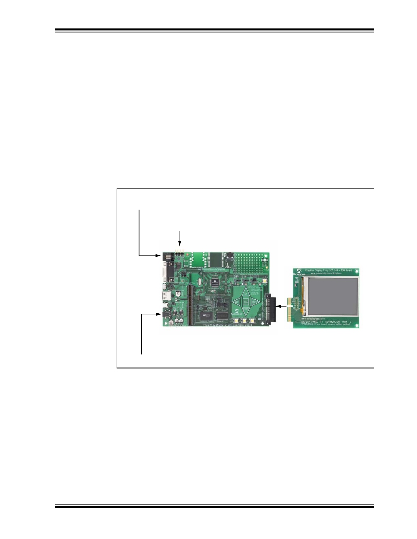
shown in Figure 1-4. To run the pre-programmed demo application:
1. Connect the Truly 3.2” Display Board display into Display Connector V1 (depend-
ing on the development board kit ordered, this may or may not be included with
the development board)
2. Plug a 9V power supply into J1
To program the board for application development, use one of the two programming
ports provided:
? J10, a 6-wire RJ-11 jack (for use with MPLAB ICD 3 and MPLAB REAL ICE
programmers)
? J9, a 6-pin riser (for use with the PICkit 3 programmer)
See Section 4.3.5 “Programming and Debugging Interface” for additional details
on the programming ports.
FIGURE 1-4:
TYPICAL BOARD CONFIGURATION
MPLAB ? ICD3 Programmer/Debugger
or MPLAB REAL ICE? In-Circuit Emulator
OR
PICkit? 3 Programmer
PIC24FJ256DA210 Development Board
Truly 3.2” Display
(AC164127-4)
9V Power Supply (AC162039)
1.6
DEVELOPMENT BOARD DEMONSTRATION PROGRAMS
The development board is pre-programmed with a demo application designed for the
Truly 3.2” Display Board. The application automatically runs when power is applied to
the board, and shows various Microchip Application Libraries integrated into a single
The application can be reconfigured to run on other display panels. To do this, the
board must be reprogrammed with the proper HEX file. For directions on reprogram-
Additional demonstration programs are provided with the Microchip Graphics Library,
discussed in the following section. Refer to the Graphics Library Help file for details on
how to download and run the additional demo applications.
? 2010 Microchip Technology Inc.
DS51911A-page 15
发布紧急采购,3分钟左右您将得到回复。
相关PDF资料
DV164101
KIT DEV PICKIT1 FLASH 8/14PIN
DV164120
KIT STARTER PICKIT 2
DV164121
KIT PICKIT 2 DEBUG EXPRESS
DV164122
ANALYZER SRL PICKIT W/DEMO BOARD
DV164131
KIT STARTER PICKIT 3
DV164132
KIT EVAL F1 FOR PIC12F1/PIC16F1
DV243003
KIT STARTER FOR SRL MEM PRODUCTS
DVA1001
ADAPTER FOR PIC16F716 18DIP
相关代理商/技术参数
DV164101
功能描述:开发板和工具包 - PIC / DSPIC PICkit 1 8/14P Flash RoHS:否 制造商:Microchip Technology 产品:Starter Kits 工具用于评估:chipKIT 核心:Uno32 接口类型: 工作电源电压:
DV164101
制造商:Microchip Technology Inc 功能描述:TOOLS: FLASH MICROCONTROLLER (
DV164102
功能描述:开发板和工具包 - 无线 rfPICkit RoHS:否 制造商:Arduino 产品:Evaluation Boards 工具用于评估:AT32UC3L 核心:AVR32 频率: 接口类型:USB 工作电源电压:5 V
DV164120
功能描述:电路内置调试器 PICkit 2 8/14/20P Flash RoHS:否 制造商:Microchip Technology 产品:In-Circuit Debugger Kits 工具用于评估:PIC MCUs, dsPIC DSCs 用于:07-00024, AC164113 核心:dsPIC, PIC 接口类型:USB 工作电源电压:3 V to 5 V
DV164121
功能描述:电路内置调试器 PICkit 2 Debug Express RoHS:否 制造商:Microchip Technology 产品:In-Circuit Debugger Kits 工具用于评估:PIC MCUs, dsPIC DSCs 用于:07-00024, AC164113 核心:dsPIC, PIC 接口类型:USB 工作电源电压:3 V to 5 V
DV164121
制造商:Microchip Technology Inc 功能描述:ICPICKIT2 PROGRAMMER/DEBUGGER ((NW))
DV164121+TEFLCST3
制造商:Microchip Technology Inc 功能描述:KIT PICKIT2+FLOWCODE-HOME BUNDLE 制造商:Microchip Technology Inc 功能描述:ICD, PICKIT 2, FLOW CODE, PIC, DSPIC 制造商:Microchip Technology Inc 功能描述:ICD, PICKIT 2, DEBUG EXP, FLOW CODE, PIC, DSPIC; Silicon Family Name:PIC12F6xx, PIC16F5xx; Core Architecture:PIC; Core Sub-Architecture:PIC12, PIC18, PIC24; IC Product Type:Debugger / Programmer; Series:PICkit 2 ;RoHS Compliant: Yes
DV164122
功能描述:界面开发工具 PICkit Ser Analyzer RoHS:否 制造商:Bourns 产品:Evaluation Boards 类型:RS-485 工具用于评估:ADM3485E 接口类型:RS-485 工作电源电压:3.3 V
